Protection & control
Relays, interlocks, trip circuits and monitoring.
Integrated electrical substation systems
Project location: Kosovo. Bring transformation, MV/LV distribution and protection together around your project. Explore integrated substation configurations for industrial, utility and infrastructure applications.
Illustrative configurations; equipment, ratings and supply scope require HKXR project confirmation.
02System architecture
A substation transformer is one component. An integrated substation also defines switching, distribution, protection and the interfaces between equipment and the site.
Source, voltage & fault level
Switching, isolation & protection
Voltage transformation
Incoming & outgoing protection
Connections to project loads
Relays, interlocks, trip circuits and monitoring.
CT/VT interfaces and utility or owner requirements.
AC/DC supplies for controls and operational duties.
Earth bonds, neutral arrangement and site earth grid.
Segregation, ventilation, access and environmental protection.
Terminations, entry positions and supply boundaries.
03Solution configurations
Four concept configurations for engineering discussion, not verified HKXR standard products or delivered systems.
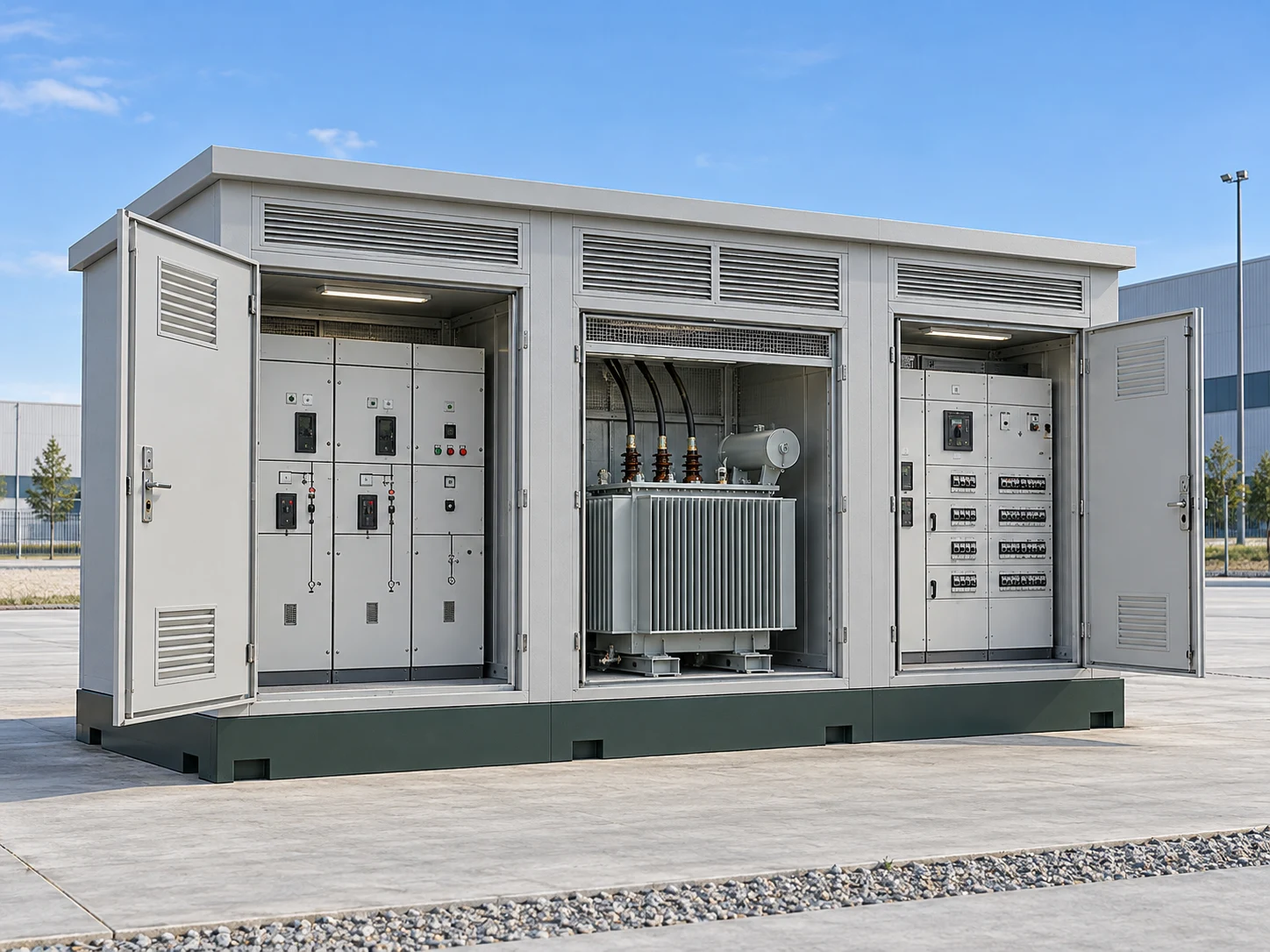
A / Integrated equipment arrangement
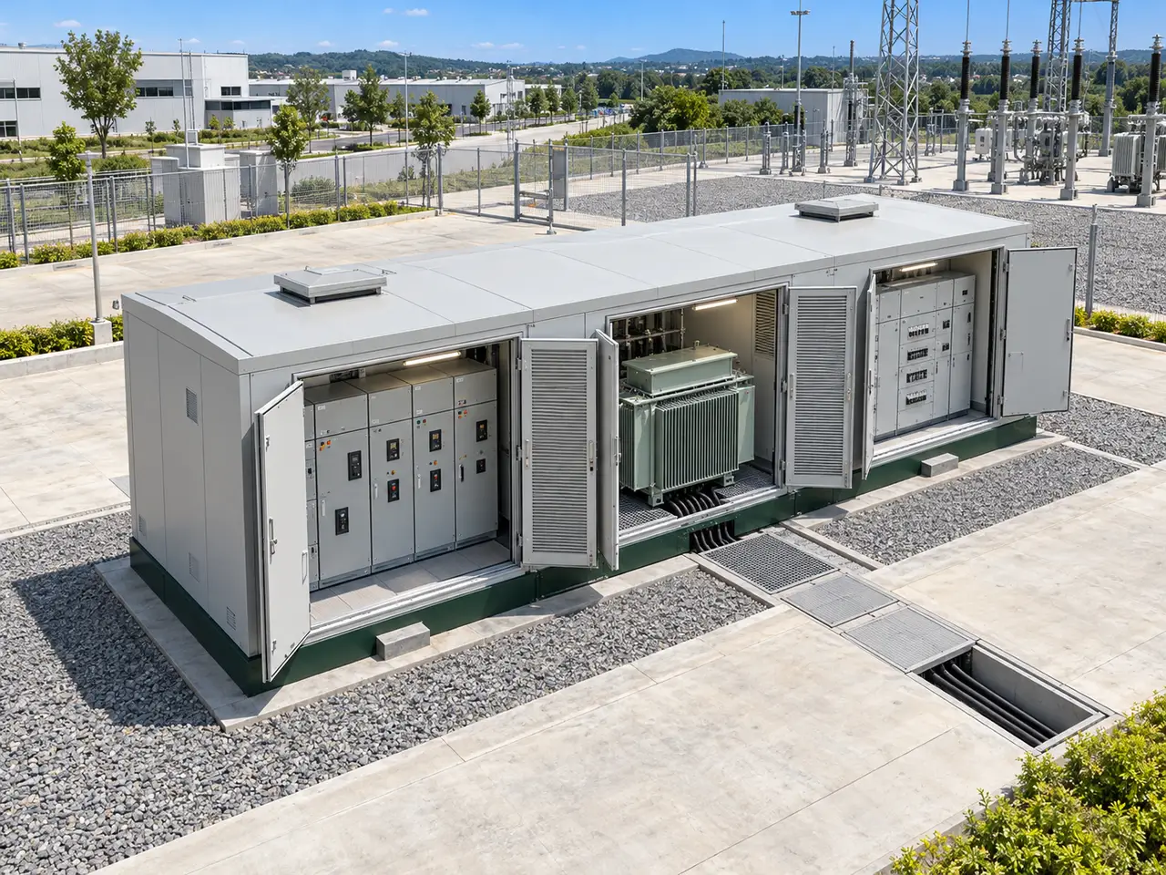
MV switchgear, a distribution transformer and LV distribution arranged in segregated compartments within a compact enclosure. A package substation brings these functions together around a defined site footprint.
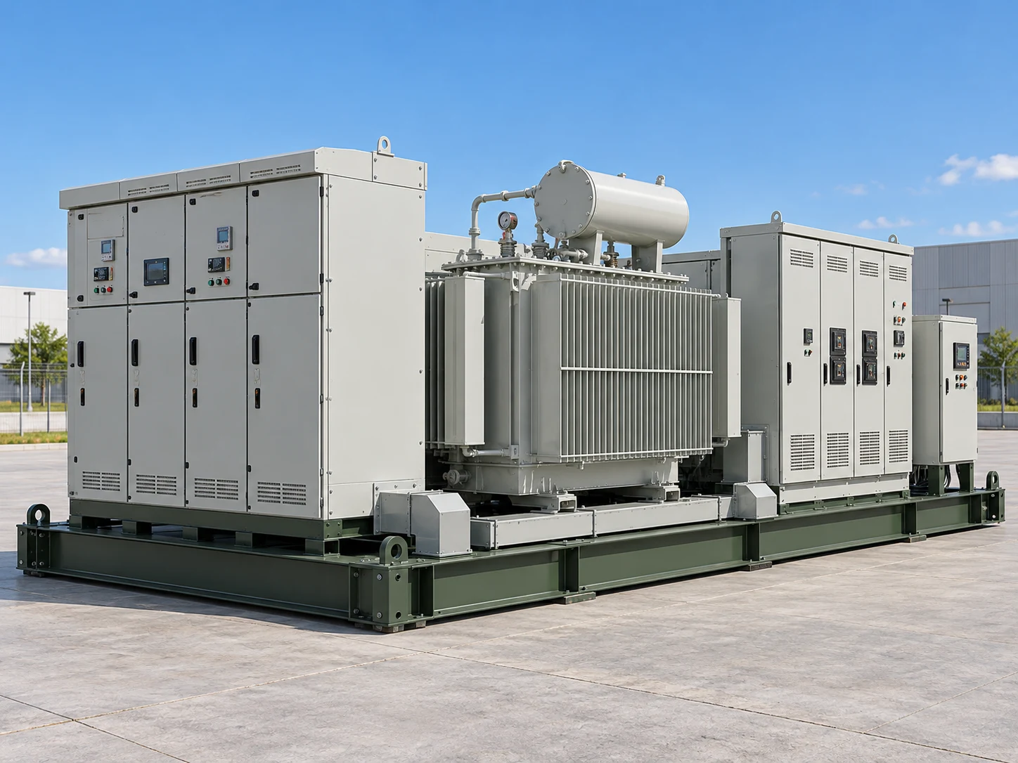
B / Integrated equipment arrangement
Transformer, switchgear and protection equipment assembled on a common structural base. Modules can be arranged for the available space and lifted or transported as an agreed assembly.
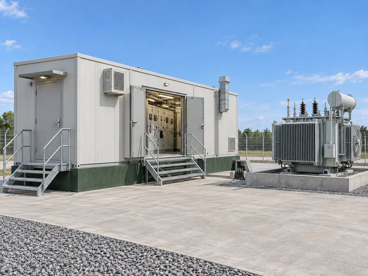
C / Integrated equipment arrangement
A prefabricated electrical enclosure can house MV/LV switchgear, protection, control and auxiliary systems. The transformer may be in a separate compartment or outside the electrical house, according to the design.
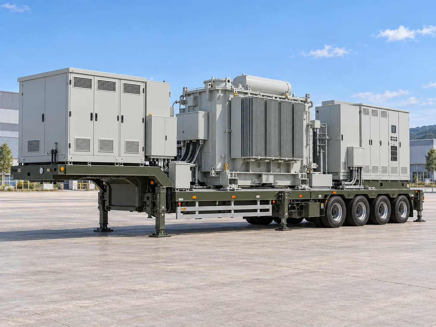
D / Temporary & relocatable systems
A transportable system combining a transformer, switchgear, protection/control equipment and electrical interfaces on one or more engineered trailers or transport platforms. The platform and deployment arrangement are part of the system specification.
| Project consideration | Compact package | Skid-mounted | Containerized / E-House | Mobile / trailer-mounted |
|---|---|---|---|---|
| Main electrical interfaces | Incoming MV cables · LV feeders · earth grid | Cable terminations · inter-module links · earth bonds | Transformer cables · control signals · auxiliary supply | Temporary incoming/outgoing connections · controls · site earth |
| Deployment requirements | Fixed plinth; cable trenches and access clearances | Engineered lifting plan, supports and site cable connections | Foundation, enclosure access, fire and environmental review | Transport permits as required, stable site and commissioning plan |
| Mobility | Fixed | Relocatable with engineering | Fixed or relocatable by design | Transportable |
04Engineering applications
Coordinate transformer loading, motor starting and feeder discrimination with the plant load schedule. Provide fault levels, harmonic loads and continuity requirements.
Align the incoming arrangement, metering, interlocks and remote-control interfaces with the network operator’s connection requirements and protection policy.
Plan the substation footprint, fire separation, maintenance routes and expansion interfaces alongside civil works and the project installation sequence.
Modular assemblies can suit restricted site resources. Check access roads, altitude, dust, corrosion exposure, lifting equipment and available auxiliary supplies.
Relocatable systems can connect a temporary load to an available source. Confirm connection capacity, operating period, cable routes, grounding and recommissioning at each site.
A mobile arrangement can bridge an outage when compatible equipment and a suitable supply are available. Verify fault duty, protection settings, transport access and safe energization procedures.
05Project configuration
Choose a configuration direction and enter the project requirements you know. Add available electrical, installation and transport details to your project brief.
06Technical considerations & standards
Define the network arrangement, load profile, insulation levels and prospective short-circuit duty at each bus. Equipment ratings must be coordinated across the system.
Review transformer impedance, inrush, vector group, neutral arrangement, switching duty and the MV/LV current ratings together. Confirm cable or busbar interfaces and thermal performance.
Specify the protection study, relay functions, CT/VT requirements, trip supplies, interlocks, metering accuracy and any SCADA protocol or signal list. Agree settings and testing responsibilities.
Define the earth-grid interface, neutral earthing, touch/step-voltage assessment, cable entries and termination responsibilities. Confirm civil foundations and oil containment where needed.
Provide ambient temperature, altitude, humidity, pollution, corrosion and seismic conditions. Review ingress protection, ventilation, fire separation and safe maintenance access.
Agree module sizes, mass, lifting provisions, road/axle limits and the assembly sequence. Mobile systems also require stability, ground-bearing and repeated-deployment checks.
Agree the applicable editions, destination rules, utility requirements and test/verification scope in the project specification. These references are not a declaration of certification, tested ratings or approval of an HKXR substation system.
Discuss compliance & engineering documents07Project information
Prepare the electrical, physical and interface information below so the equipment scope and responsibilities can be agreed before quotation.
Show incoming and outgoing circuits, transformers, bus sections, protection and metering. Include load data and electrical specifications.
Confirm the footprint, access clearances, transformer location, enclosure layout, cable entries and transport envelope.
Identify internal wiring, external cables, auxiliaries, earth connections, civil works, installation and commissioning responsibilities.
SLD, specifications, equipment list and site conditions.
Confirm feasibility, interfaces and open technical questions.
Define equipment, documents, tests and site responsibilities.
Issue a project-specific offer against the agreed requirements.
08Decision support
A compact package groups MV switching, transformation and LV distribution in an integrated enclosure with defined internal interfaces. A conventional site-built arrangement can use separately installed equipment and buildings. Compare maintenance access, ventilation, fault duty, public access protection, expansion and civil works rather than footprint alone.
Start with the single-line diagram, source and load voltages, load profile, fault levels and continuity requirements. Then assess environment, available space, access and installation method. A compact, skid, E-House or mobile arrangement is an engineering choice; the final equipment combination and supply scope need project review.
Their ratings, protection, cable or busbar connections, earthing, interlocks and thermal conditions are coordinated as a system. Equipment can share an enclosure or base, or be connected as separate modules. The agreed drawings must define equipment boundaries and every site connection.
No. An E-House typically provides an electrical equipment environment for switchgear, protection and control. The transformer may be outside or in a separate compartment, depending on ventilation, fire separation, access and the project specification. Containerized and E-House arrangements should be defined by their function and layout.
A mobile or relocatable configuration may be considered for temporary connections, planned maintenance or restoration after an outage. Confirm a suitable incoming supply, voltage compatibility, transport restrictions, site stability, grounding, cable interfaces and commissioning. HKXR must confirm project feasibility and the proposed supply scope before quotation.
Send the single-line diagram, equipment list, electrical specifications, load schedule and site layout if available. Include installation conditions, transport/space limits, protection and metering requirements, destination, schedule and proposed scope of supply. If drawings are not ready, identify the missing information for the initial review.
Identify the destination, utility rules, project specification and the standards applicable to each component and the assembled system. Agree the editions, verification evidence, routine/type/special tests and witnessing requirements in the technical offer. Referencing a standard on this page is not a claim of system certification.
Define the supply boundary in the quotation: equipment, internal wiring, external cables, civil works, earth grid, unloading, assembly, testing and energization. Identify the owner, EPC, installer and manufacturer responsibilities in an interface schedule. Installation and commissioning are not automatically included with equipment supply.
09 / Let’s discuss your project
Share the single-line diagram, equipment list, electrical specifications, installation conditions and proposed scope of supply.
Alternative contact
Select a system configuration or describe your project requirements.
Edit configurationUse WhatsApp or the simple email contact below to share your project. Your selected configuration is included.
Discuss your projectEmail project inquiry